 Huli huahana
ZN-L1580 Kikowaena Mīkini Vertical
Cat:Kikowaena Mīkini Vertical
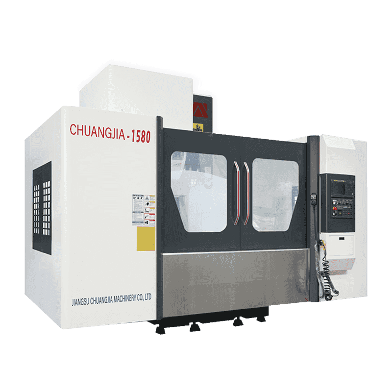
Hoʻopaʻa ʻia kēia moʻo o ka machining center i loko o ke kolamu hoʻokahi A-shape, mobile structure of workbench, rigidity kiʻekiʻe o nā ʻāpana kumu...
E nānā i nā kikoʻī
Pick up a machine inspection report for a large mold or structural frame part and the story is usually the same: the geometry problem appears only after the first finishing pass, not on the job list. In a CNC gantry machining center, the root cause is rarely one faulty component. It is the interaction between the gantry frame, spindle, drive system, control loop, and supporting systems. Get those key components right, and you get a machine that removes metal fast, holds tolerance over long travels, and repeats it shift after shift. Get one wrong, and the rest of the machine must compensate.
The structural loop is the set of castings that resist cutting force: bed, worktable, columns, beam, ram, and the connections between them. Rigidity matters because it acts as the chassis for the entire machining process. In a large gantry, this is more important than spindle power. If the loop deflects under load, every axis movement is measured from the wrong reference, and the error grows along the travel length.
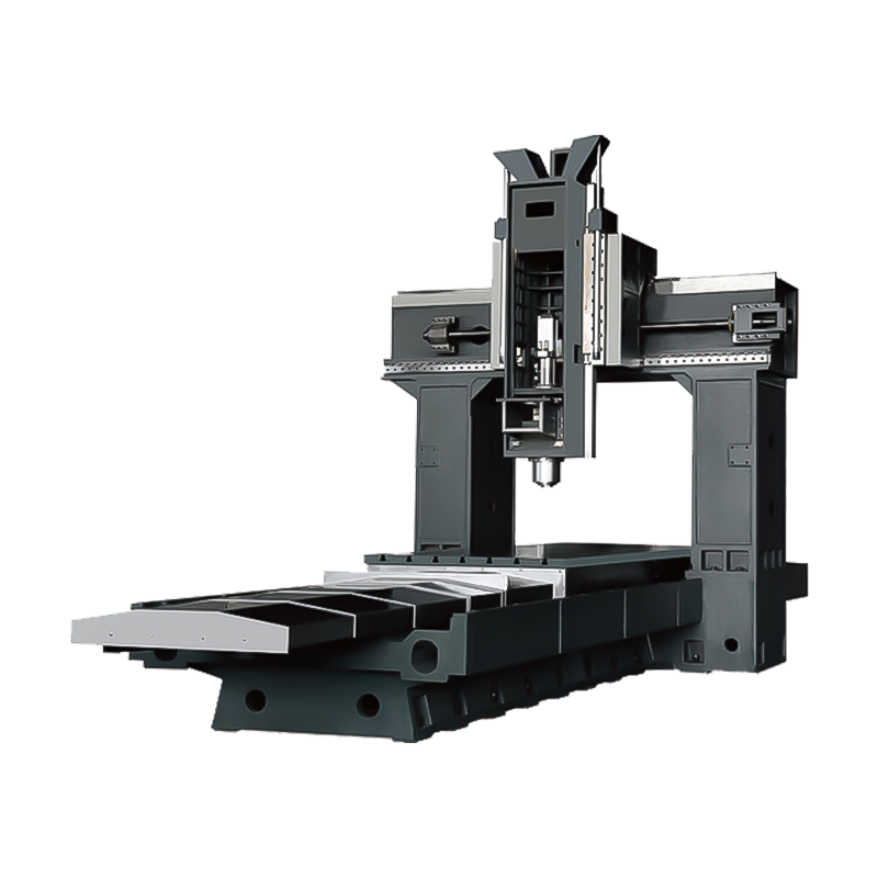
The beam and columns form a bridge over the worktable. A moving-table gantry keeps the gantry stationary and feeds the workpiece through the machine; this layout is compact and easy to enclose, so most smaller gantry machines use it. A moving-gantry design keeps the workpiece stationary and moves the gantry on bed rails. That suits parts longer than the machine itself, such as long frames, spars, and molds that are awkward to move once they are set up.
The worktable may look like a simple plate with T-slots, but it is part of the structural loop. A heavy table resting on a rigid bed with linear guides distributes clamping forces more evenly and avoids twisting under asymmetric loads. Material selection follows the same logic: cast iron is heavier and dampens chatter, while steel weldments can be stiff but require stress relief and generous ribbing. For wide workpieces, a closed frame that supports both sides of the beam is better than an open-sided machine. That is where a double-column gantry machining center earns its reputation: the beam is held symmetrically by both columns, so the stiffness envelope stays tight across the table.
The spindle system is not an isolated cartridge. On a gantry machine it sits inside a moving ram assembly that also carries the Z-axis feed. The ram needs a large cross-section, symmetrically guided contact faces, and enough bearing support to keep the spindle axis perpendicular to the table under side loading. If the ram twists, you see it as taper mismatch or poor finish on long vertical walls.
For general milling, a belt-driven spindle with a BT50 or SK50 taper is common because it can deliver high torque at moderate speeds while dampening vibration. For finishing work and faster cycles, direct-drive or built-in spindles reduce vibration and run smoother at higher rpm. The spindle taper matters more than the maximum rpm in a gantry: a heavy machine tool with a stiff taper can remove more metal per hour than a high-speed spindle that stalls under load.
When the application involves 3D surfaces, a tilting head raises the capability of the machine. A 5-axis gantry machining center adds rotary axes to the spindle head, which lets the tool reach angled surfaces without repositioning the workpiece. That is not a luxury for mold inserts or turbine components; it reduces setups and improves surface continuity. But a five-axis head also adds weight to the ram, so the structural loop must be designed for that additional mass.
The drive system has to do two things at once: move to an exact position and hold that position while cutting forces push against the tool. Servo motors and amplifiers provide the actual motion, but the transmission determines how smooth and repeatable it is. On short Y and Z travels, preloaded ball screws are the first choice because they convert rotary motion into linear motion with low friction and predictable backlash. On the long X-axis, a large-diameter ball screw becomes prone to whipping at speed. Many gantry designs use a preloaded rack-and-pinion drive on each side of the beam with a master-slave servo loop. The preload removes mechanical backlash; the electronic synchronization keeps the beam from twisting.
Linear guideways give low friction and high straightness. Box ways give more damping for heavy cutting. In a gantry, the practical compromise is often preloaded linear guides on the X and Y axes and a heavy ram guided by box ways or large linear bearings. The important point is not which system is better in theory but whether the guideway was sized for the cutting load and protected from chips.
Feedback is the part most buyers overlook. Servo motor encoders only measure the motor position, not the position of the table or ram. Linear scales mounted directly on the machine axes measure actual displacement and automatically compensate for thermal growth of the screw or rack system. Component selection should therefore be evaluated together: ball screw, guideways, servo size, and scale placement all work as a loop.
The table below puts these components side by side and lists what to check when comparing machine specifications.
| Component | Primary role in machining | What to verify |
|---|---|---|
| Gantry frame | Resists cutting forces and defines the stiffness envelope | Cast iron vs. steel, symmetric column supports, beam and ram cross-section |
| Spindle and ram | Rotates the tool and supports Z-axis cutting loads | Bearing size, ram diameter, spindle taper, head type |
| Axis drives and transmission | Moves and holds each axis under load | Ball screw vs. rack-and-pinion, preload method, servo sizing |
| Guideways | Provide smooth and precise motion | Linear vs. box ways, preload class, chip protection |
| Feedback system | Measures actual axis position | Linear scale resolution, mounting location, scale type |
| Tool management | Cuts manual setup time | Magazine capacity, ATC cycle time, tool interface |
| Coolant and lubrication | Controls heat, chips, and friction | Coolant pressure, filtration, automatic lubrication points |
| Control system | Coordinates axes and process logic | Look-ahead, axis synchronization, expansion options |
Beyond the structural components, a gantry machining center is made productive by the systems that keep it running. The CNC control coordinates three or more axes plus auxiliary functions. For a dual-motor gantry X-axis, the control must handle synchronized motion; otherwise small following errors cause the beam to bind. Look for processing power that can handle smooth 3D contouring with high look-ahead, because a large machine can lose accuracy if the control has to pause at every block.
The tool magazine and automatic tool changer matter more on a gantry than on a simple mill. Heavy tools are too awkward to change by hand. A magazine with enough stations for the complete process reduces setup, and a short tool-change cycle improves utilization. Verify the tool interface: BT50 or SK50 is common for heavy milling, while HSK can be better for high-speed five-axis finishing.
Support systems should not be treated as accessories. Three deserve particular attention on a gantry machine:
If you want a more detailed look at these effects, our article on coolant and lubrication systems explains the practical impact on tool life and finish.
For a wide range of plate-type molds and structural parts, a mid-size machine is often the most economical way to combine all these components in one setup. The LM2218 gantry machining center is one example where a rigid frame, a practical magazine capacity, and a controlled axis structure are matched for typical job-shop work. It is not a machine for extremes, but it shows how component balance matters more than a single high specification.
 Custom LM2218 Double column CNC gantry machining center Suppliers, Factory - Jia Jiangsu Chuangjia Machinery Co., Ltd is China custom LM2218 Double column CNC gantry machining center suppliers and LM2218 Double column ... View Product →
 Comparing machines only by spindle RPM, travel range, or price misses the point. The key components of a CNC gantry machining center are a system: the frame decides how much force you can apply; the spindle and ram decide how accurately that force reaches the tool; the drives and scales decide how faithfully the coordinates are reproduced; and the control, coolant, and chip management decide whether the whole loop remains stable over a long shift. When a machine is engineered with matched stiffness and feedback, the benefits show up in predictable cycle times, reliable tolerances, and fewer scrapped workpieces. That is why you should review the structural build, feed drive design, and feedback strategy before signing an order. You can start by comparing specifications in a gantry machining center lineup , then ask the supplier to explain how each component handles your specific part size and cutting load.
Hoʻopaʻa ʻia kēia moʻo o ka machining center i loko o ke kolamu hoʻokahi A-shape, mobile structure of workbench, rigidity kiʻekiʻe o nā ʻāpana kumu...
E nānā i nā kikoʻī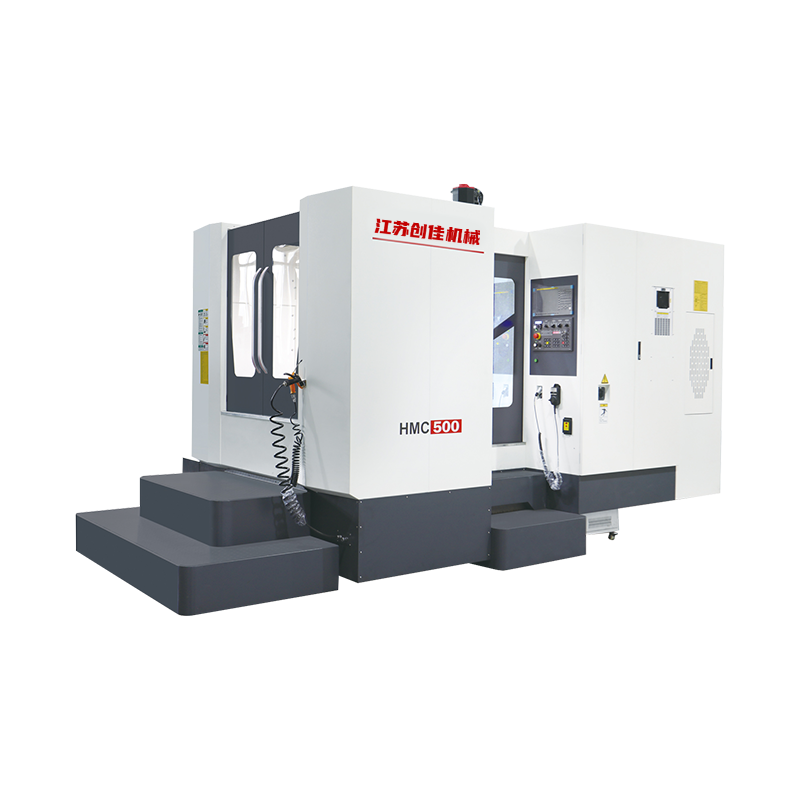
Hoʻohana ka moena i ka hoʻohei T hoohuli ʻia, neʻe ka pākaukau (X axis), neʻe ke poʻo i luna a i lalo (Y axis) a neʻe ke kolamu i hope a i waho (Z ...
E nānā i nā kikoʻī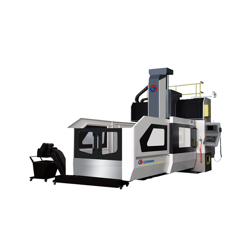
Hoʻohana ʻia ka ʻaoʻao e kākoʻo ʻekolu-axis o kēia moʻo o ka gantry machining center i ke alakaʻi laina laina koʻikoʻi, maʻalahi ka mālama ʻana, ha...
E nānā i nā kikoʻī
Hoʻohana ka hopena i ke ʻano hana o ke ʻano gantry paʻa a me ka neʻe ʻana i ka papa ma luna o kahi moena. ʻO ka hoʻokomo hoʻohui ʻia o ka kolamu Be...
E nānā i nā kikoʻī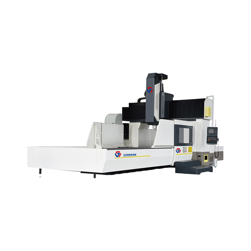
Hoʻohana ka hopena i ke ʻano hana o ke ʻano gantry paʻa a me ka neʻe ʻana i ka papa ma luna o kahi moena. ʻO ka hiki ke hoʻohui ʻia ʻo Beam column,...
E nānā i nā kikoʻī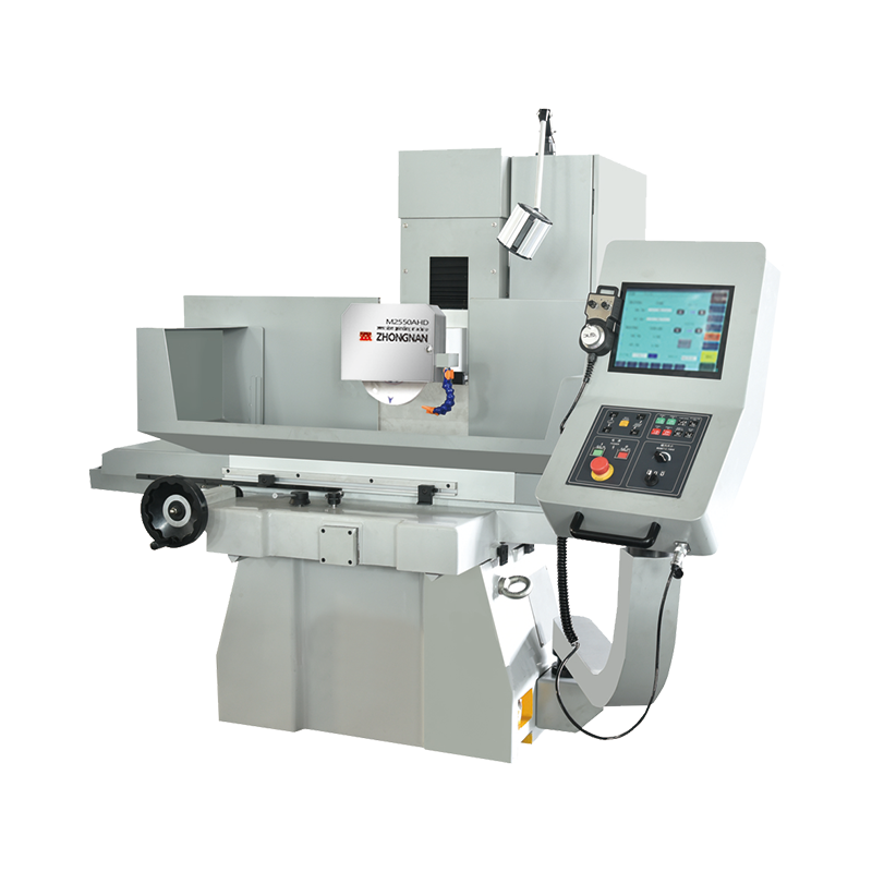
Kiʻekiʻe kiʻekiʻe / kiʻekiʻe wikiwiki / maʻalahi i ka hana ʻana i ka hopena honua CNC X axis hydraulic / YZ axis servo / ʻōnaehana CNC. Hoʻoikaika ...
E nānā i nā kikoʻī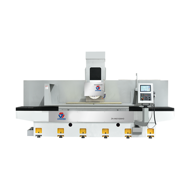
ʻO ka paʻahana ka mea kūpono no ka wili pololei ʻana o nā mea metala like ʻole, e like me ka mokulele, ka paepae a me ke ʻano kikoʻī, a hoʻohana nu...
E nānā i nā kikoʻī
ʻO ka paʻahana ka mea kūpono no ka wili pololei ʻana o nā mea metala like ʻole, e like me ka mokulele, ka paepae a me ke ʻano kikoʻī, a hoʻohana nu...
E nānā i nā kikoʻī
All rights reserved Jiangsu Chuangjia Machinery Co., LTD.
